The 75mm Pack Howitzer Gun
Special thanks to Mr. Matthew Seelinger, Chief Historian, and Mr. Seth Paltzer, Assistant Historian,
The Army Historical Foundation, Arlington, VA.
Article from The American Arsenal:
The World War II Official Standard Ordnance Catalog of Small Arms, Tanks, Armored Cars, Artillery, Antiaircraft Guns, Ammunition, Grenades, Mines, Etc.
This book is essentially a 1996 reprint of Catalog of Standard Ordnance Items , produced by Office of the Chief of Ordnance Technical Division in 1944. The reprint was published by Greenhill Books of London, UK.
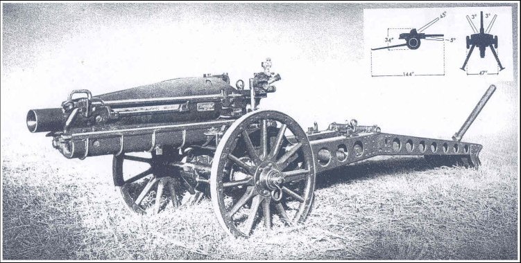
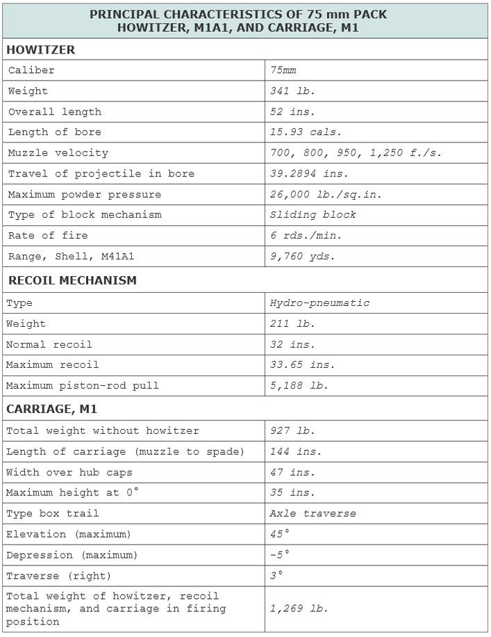
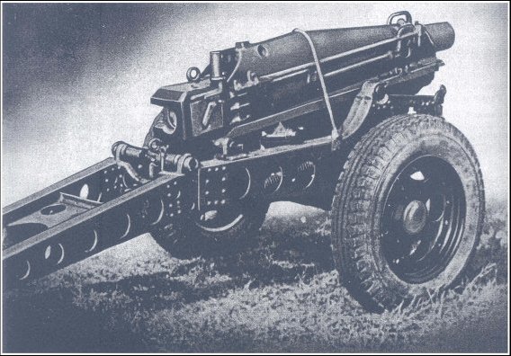
75 mm PACK HOWITZER, ON CARRIAGE, M1
The 75 mm pack howitzer was originally designed for pack transport, animal draft, and low-speed towing. Animal draft has been discontinued and the special accessories made obsolete. In modified form it has been adopted for many uses.
Development of the weapon, begun in 1920, culminated in standardization of the M1 in 1927. Slight changes in the M1 were made later, and the new model given the designation of M1A1. The primary use of this howitzer was for operation in mountainous terrain. With the round H.E., A.T., M66, the M1A1 howitzer is capable of engaging antitank targets, as the projectile will penetrate 3 inches of armor plate at howitzer range.
HOWITZER, M1
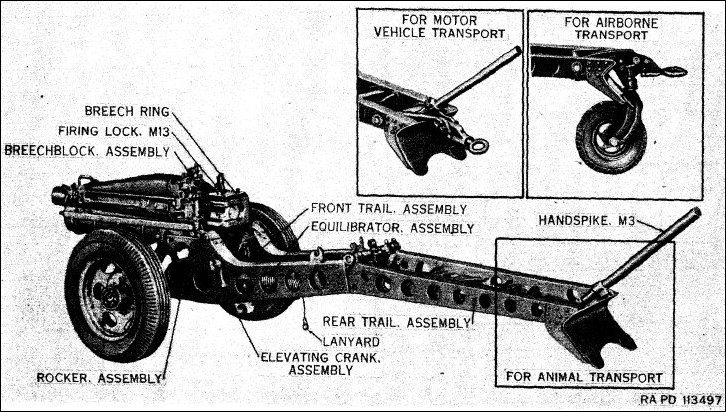
The Howitzer, M1, consists of a tube assembly and a breech mechanism, joined by interrupted threads for rapid assembly and disassembly. The breechblock is of the hand-operated, sliding-wedge type. Firing is accomplished by a continuous-pull mechanism known as Firing Lock, M13. The tube and breech mechanism comprise two loads for transport.
HOWITZER, M1A1
This howitzer differs from the M1 only in slight modifications of the breech ring and the breechblock. These parts are not interchangeable in the two models.
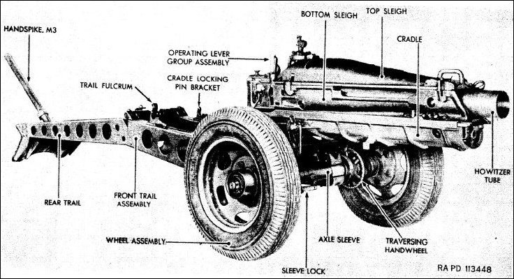
PACK HOWITZER CARRIAGE, M1
This carriage is separated into six loads for pack transport. It has a hydropneumatic recoil system composed of a recoil cylinder and a recuperator cylinder connected with the bottom sleigh which forms a seat for the howitzer and maintains alignment of the tube and breech ring when assembled. A top sleigh covers the howitzer and retains it in the bottom sleigh. Steps on the bottom sleigh are fitted to ways on the cradle, and the recoil-cylinder piston rod is connected to the cradle by means of the piston rod latch. In recoil and counterrecoil, the cylinders and bottom sleigh move with the howitzer, while the cradle remains stationary. Traverse is along the axle, accomplished by a traversing nut operated by a handwheel.
Rockers, which pivot on trunnion pins, are located on either side of the cradle.
The box trail is divided into two groups, the front trail and the rear trail, fastened together by fittings strong enough to withstand firing stress. The elevating mechanism, rockers, and equilibrators are assembled to the front trail and are carried with it in the pack. The wheels are of wood with steel tires.
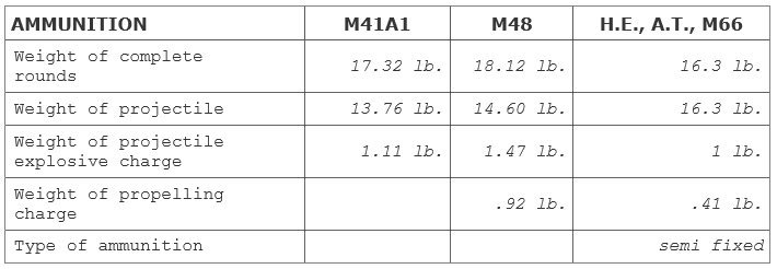
AMMUNITION
Ammunition for the 75 mm Pack Howitzer, M1A1, is in the form of semi-fixed rounds. It consists of H.E. Shell, M41A1, with P.D. Fuze, M48; H.E. Shell, M48, with P.D. Fuze, M48, and T. & S.Q. Fuze, M54; and H.E., A.T. Shell, M66, with B.D. Fuze, M62.
Sighting and Fire Control Equipment
On Carriage Equipment
Panoramic Telescope, M1
Telescope Mount, M3
Off Carriage Equipment
Bore Sight
Gunner's Quadrant, M1
Aiming Circle, M1
Compass, M2
1-Meter-Base Range Finder, M7 or M1916
B.C. Telescope, M65 or M1915A1
Trainer
The 37 mm Subcaliber Gun, M1916, and Subcaliber Mount, M5, are used for practice in laying and firing the 75 mm Pack Howitzers, M1 and M1A1.
REFERENCES: TM 9-2005, v.3; TM 9-320; TM 9-1320.
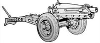
CARRIAGE (AIRBORNE), M8
The 75 mm Pack Howitzer Carriage, M8, was developed to provide airborne troops with a light, powerful weapon which could be transported as a unit to the combat area by glider or airplane. When the airplane lands at its destination the howitzer and carriage can be unloaded and maneuvered into position by hand or be towed by a prime mover. The howitzer and carriage can also be disassembled, packed in paracrate loads, and dropped by parachutes from an airplane in flight. When the paracrates reach the ground the individual loads are unpacked and the howitzer and carriage are assembled for action.
The standard 75 mm Pack Howitzer, M1A1, is mounted on the Carriage, M8. This carriage is identical to the 75 mm Pack Howitzer Carriage, M1, except for the substitution of steel disk and rim type wheels equipped with 6.00 x 16 pneumatic tires in place of the 29 inch wooden wheels used on the M1 carriage.
REFERENCES: OCM 20196; TM 9-319.
Sighting and Fire Control Equipment
On Carriage Equipment
Telescope Mount, M3
Telescope Adapter, M9
Elbow Telescope, M62
Off Carriage Equipment
Gunner's Quadrant, M1
Aiming Circle, M1
Hand Fuze Setter, M1912A4, M15, or M16
75 mm PACK HOWITZER, M8, FOR AIRBORNE USE
From the Technical Manual TM 9-319
75-mm Pack Howitzer M1A1 and carriage M8 - left rear view
75-mm Pack Howitzer M1A1 and carriage M8 - right front view
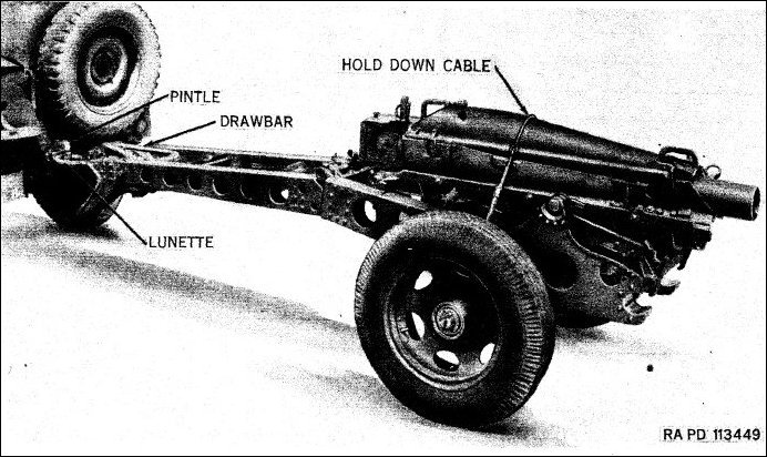
75-mm Pack Howitzer M1A1 and carriage M8 - in towing position
PARACRATES M1, M2, M3, M4, M5, M6, M7, Parachest M8, Paracaisson M9
In order that the disassembled 75 mm Pack Howitzer, M1A1, and Carriage, M8, together with fire control instruments, and accessories, could be safely delivered by parachute from an airplane in flight, a series of containers known as paracrates, parachest, and paracaisson, were evolved to hold the nine loads to be dropped. Fabrication of these containers was begun in September, 1942, and they were standardized in May, 1943, as Paracrates, M1 to M7, Parachest, M8, and Paracaisson, M9.
Paracrates, M1 to M7, are constructed of plywood, each paracrate being designed to accommodate a specific load. When the load is packed it is secured to bomb shackle and parachute harnesses by means of a quick-release fastening. A standard 24-foot cargo parachute is attached to each load, the parachutes being colored to differentiate between the loads and hasten identification.
Paracrate Loads, M1 to M5, together with Paracrate Load, M9, are fastened to and dropped from parachute pack racks beneath the airplane. Paracrate Loads, M6 and M8, are carried as a daisy-chain load inside the fuselage, from which they are pushed out through the doorway of the airplane.
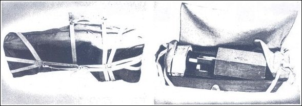
PARACRATE, M1 (FRONT TRAIL), CRATE SUSPENDED (Left)
AND PARACRATE, M2 (REAR TRAIL AND AXLE), CRATE LOADED (Right)
PARACRATE, M1
This paracrate consists of front and rear reinforces and a wooden brace for the howitzer front trail assembly, together with a canvas paracrate cover with parachute harness attached. When packed it holds the front trail and a lifting bar.
PARACRATE, M2
Paracrate, M2, includes a canvas cover with parachute harness attached, wooden supports, and a wooden hexagonal reinforcing housing. The load comprises the howitzer rear trail, axle and traversing mechanism assembly, trail handspike, sponge staff, aiming post sleeves, and a box containing spare parts and tools.
PARACRATE, M3
This paracrate is in the form of a plywood box with pentagonal ends and a hinged cover. The load consists of the howitzer bottom sleigh and recoil mechanism, a lifting bar, an aiming circle with case, circular wooden supports, a shock block, and a shock pad.
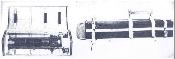
PARACRATE, M4 (CRADLE AND TOP SLEIGH), CRATE LOADED (left) AND
PARACRATE, M5 (TUBE), CRATE SUSPENDED (right)
PARACRATE, M4
Paracrate, M4, is similar in shape to Paracrate, M3. The load is made up of the top cradle and sleigh of the howitzer, a shock block, and a shock pad. Paracrates, M3 through M6, have the bomb shackle and parachute harnesses separated from the paracrates.
PARACRATE, M5
This paracrate is a rectangular plywood box with a hinged lid. Its load is composed of the howitzer tube, a muzzle cover, a tube thread cover, a lifting bar, lifting straps, a shock block, and a shock pad.
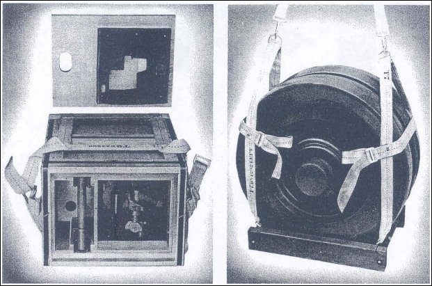
PARACRATE, M6 (BREECHBLOCK AND SIGHT), CRATE LOADED (left) AND
PARACRATE, M7 (WHEELS), CRATE SUSPENDED (right)
PARACRATE, M6
Paracrate, M6, is a rectangular plywood box with a detachable padded lid. The load consists of the howitzer breech mechanism, the hub caps, the panoramic telescope and telescope mount in a special container, the telescope mount support, and a lifting strap.
PARACRATE, M7
Paracrate, M7, consists of a square wooden frame, the inner sides of which are beveled. The parachute harness is attached to the frame. The load is composed of the howitzer wheels and hub plugs.
PARACRATE, M6 (BREECHBLOCK AND SIGHT), CRATE LOADED (left) AND
PARACRATE, M7 (WHEELS), CRATE SUSPENDED (right)
PARACHEST, M8
This parachest is made of plywood, and consists of a large section to which a slightly smaller section is added as a continuation. The cross section of each portion is six-sided, in the form of a square on which is imposed a truncated triangle. The front end of the large section is hinged, so that it can be opened for loading. The parachute harness is separate and when assembled on the parachest has skids lashed to it to facilitate landing. The load is composed of ten complete rounds of 75 mm howitzer ammunition, each of which is packed in a fiber container.
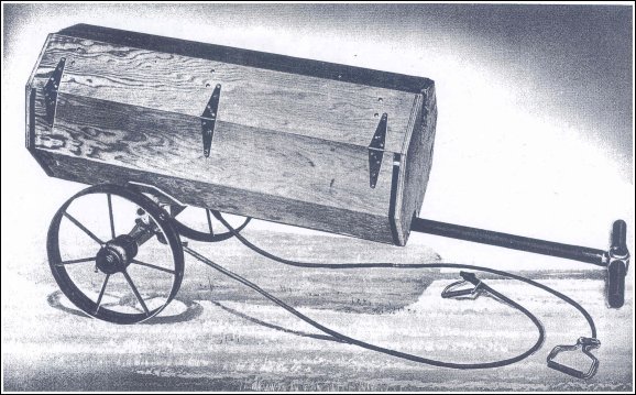
PARACAISSON, M9, (AMMUNITION CART), CART ASSEMBLED
PARACAISSON, M9
Paracaisson, M9, is a manually drawn, knockdown cart with a plywood body of hexagonal cross section, demountable steel wheels, and an axle assembly, drawbar, tongue,
and drawlines, all of which can be packed in the body when the paracaisson is disassembled for transport. A wheel spacer, a brace support, a drawbar tray, an axle tray, tray side braces, and tray top braces are utilized in packing the components of the paracaisson. The bomb shackle and parachute harness are separate.
The paracaisson is used to transport ammunition, eight complete rounds in individual fiber containers constituting a full load. When assembled, the paracaisson is normally pulled by two men who grasp the drawbar at the free end of the tongue. When it is necessary for four men to tow the cart two drawlines are attached to the axle by means of drawline hooks which hook through holes in the axle.
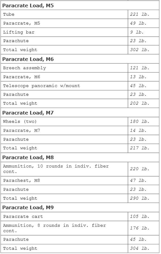
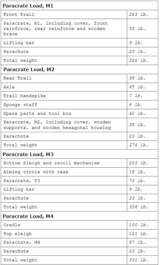
The howitzer, caisson and cart, with ammunition, are packed in nine paracrate loads having a total weight of 2,571 pounds. The component parts of these loads and the equipment required for assembling them are as follows:
Extra Inquiry
Question : How did one load the 75mm Pack Howitzer and drop it ?
Courtesy 1. Douglas - Doug - Bailey (WWII veteran 463PFA)
Courtesy 2. Article ‘Field Artillery’, July-August 2000, “Cannons under Canopy”, by Major Scott T. Glass, QM.
American airborne Field Artillery units in World War II primarily employed the M1A1 75-mm pack howitzer on an M8 carriage. Initially designed in the 1920s as a weapon for disassembly into loads carried by mules, it delivered a 14-pound (6.35 kg) shell to a maximum range of 9,610 yards (8787 meter).
The artillery community later developed the M8 carriage specifically for airdrop operations.
The gun weighed 1,339 pounds (607 kg), and during the opening phases of airborne operations, the gun crews wheeled it by hand without a prime mover as standard practice. Indeed, the doctrinal manual for airborne Field Artillery at the time recognized crew muscle as the prime means of moving guns on the airborne battlefield.
The 75-mm howitzer’s relatively small size and weight allowed disassembly into nine paracrate or parapack loads containing gun components and ammunition.
The 75-mm howitzer’s relatively small size and weight allowed disassembly into nine
paracrate or parapack loads containing gun components and ammunition.
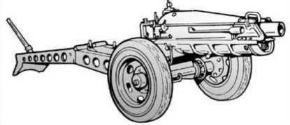
The versionshown here is the M1A1 on the M1 (M116) carriage
1. Front Trail Section and Drawbar
2. Axle, Rear Trail Section and Toolbox
3. Sleigh and Gun Cradle
4. Top Gun Cradle
5. Cannon Tube
6. Breechblock and Sights
7. Carriage Wheels
8. 10 Ready Rounds of Ammunition
9. Paracaisson Handcart of Eight Additional Rounds
Gun crews packed loads One through Five and Nine and attached them to fuselage and wing racks of C-47 transport aircraft. The jumpmaster released the bundles over the drop zone (DZ) by toggling a series of switches. As he did so, gunners pushed out a bundle from the troop door containing 75-mm howitzer loads Six, Seven and Eight roped together and then followed the bundle out. A daisy chain harness connected the loads jettisoned from outside the aircraft and ensured they arrived on the DZ close together. The M1A1 had few peers at the time as an airborne indirect fire weapon, and the British airborne forces used it instead of attempting to develop a similar weapon.
Doug: the 75mm Pack Howitzer could be taken apart to be loaded on the C47. Six parapacks loaded under the C47 and a Door load of the wheels and a padded box holding the Gun sight and the Breechblock.
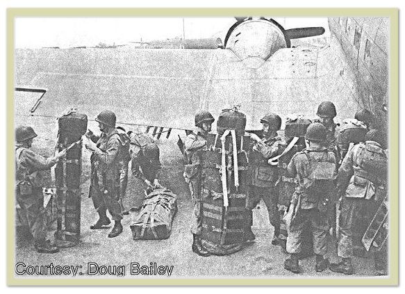
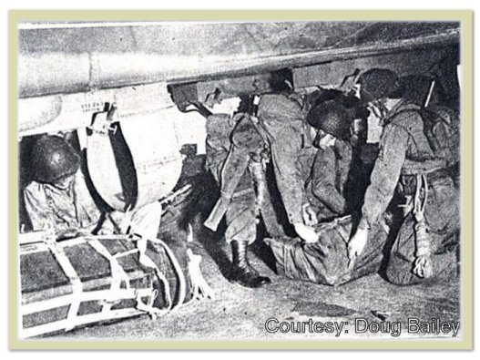
Airborne gunners prepare parapacks next to their C-47 transport.
Note the paratroopers are preparing the 75-mm howitzer bundles themselves.
Doug :
the Equipment Chute was loaded into the Pod in front, the Pod for the equipment Chute was under the center (body) of the C-47 and each of the 6 parapacks had their own Chute, also the Door load had it's own Chute. The 6 Parapacks were attached to the fuselage (underneath the body of the of the plane). Nothing was attached under the Wings.
Doug :
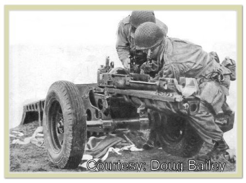
If you found all the pieces of the Gun you would assemble them.
In the Picture the Recoil system is installed and the Breech Block is in and the rear Trail is attached and the Tube or Barrel has to be added, Top Sleigh would be on top.
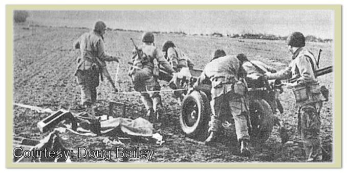
Some of the Plywood Paracrates held the ammunition and after you took the ammunition out they contained a Handle that you could pull out and also a axle with two wheels, then you would put the Ammunition back in and you could pull the Paracrate with the Ammunition.
Doug :
After you assembled the Gun and since we were not dropping any Jeeps we had to move it by Hand.
The door load consisted of the two wheels and a padded box that held the Breechblock and sight : sometimes we would attach a Daisy chain to all the bundles so if any bundles got hung up the weight of the others would pull it free to drop.
The Pilot or co-pilot could make the Bundles drop and there was a handle by the Door you could pull to release the Belly loads. we would usually have a piece of pipe or a round piece of wood to put under the door load to make it easier to push out the Door. Also they had little colored lights attached to the loads that activated when the equipment Chute opened, it would pull a piece of cardboard out and the light would go on.
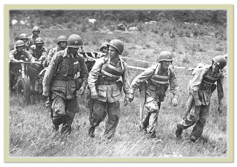
1943 photo showing a pack howitzer crew moving the gun with a system on harnesses.
These harness assemblies went in the paracrates and were dropped with the gun.
Doug, what about finding the different parts of the gun after landing ? Was it difficult ?
Filip, to find and assemble the gun depends on the area it landed. Some gun crews never even found there Gun if it landed in a gully or thick brush. In the Sicily drop I never found my Gun and crew until daylight probably because the plane I was in just carried Ammunition 75mm and Bazooka ammunition.
In the France jump I landed in a road in the middle of lots of Trees and Brush and it was also daylight when Carl Noline who was a Apache Indian from the San Carlos Indian Reservation in Arizona and I found our 4th Gun Section. We were the last two of the stick that jumped from our plane.